Guess the Photonic Component: The Answers, the Physics, and where you will find them
For Day of Photonics, we showed three small fragments of PIC layouts and asked our community to name them. Here are the answers!
Behind each one is a building block that ships in real products, from the transceivers that connect servers to biosensors and optical computing prototypes. For each component, you will get how it works, the key equation, where it is used, and one thing most people don’t know about it.
The answers in a simple way:
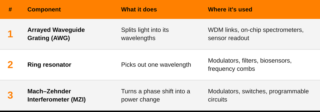
Component #1 Arrayed Waveguide Grating (AWG): The Wavelength Sorter
An AWG is a passive device used for wavelength-division multiplexing (WDM). It works through wavelength-dependent interference.
How it works:
- Light from the input waveguide spreads through a free-propagation region (FPR) and couples into an array of waveguides.
- Each array waveguide is longer than its neighbor by a fixed increment ΔL, so adjacent arms accumulate a constant phase difference.
- In the output FPR the beams recombine. The tilt of the phase front depends on wavelength, so each wavelength focuses on a different output waveguide.
Where it is used:
- WDM links: one fiber can carry up to ~96 channels (50 GHz spacing in the C-band), and an AWG separates them at the receiver. Data center transceivers use the same idea to combine four wavelengths into one 400G link.
- On-chip spectrometers for sensing and astronomy, where size and weight matter.
- Sensor readout: AWG-based photonic interrogators can monitor arrays of fiber Bragg grating sensors used in bridges, wind turbines, and aircraft.
Fun fact: At 1550 nm, a 100 GHz channel spacing corresponds to just 0.8 nm. In a conventional silicon-on-insulator AWG, a thermal drift of around 70 pm/K means that a temperature change of approximately 12 K could shift its spectrum by an entire 100 GHz channel. For a 50 GHz grid, it would take only about 6 K.
Component #2 Ring Resonator: The Optical Wavelength Filter
A ring resonator is a waveguide bent into a loop and parked next to a straight one. Most wavelengths ignore it. The ones that fit the loop get trapped and build up.
How it works:
- Light crosses the gap from the straight (bus) waveguide into the ring by evanescent coupling.
- A wavelength resonates when the field returns in phase after one lap: m · λ = n_eff · L, with L = 2πR where R is the ring radius, n_eff is the effective index, and m is an integer.
- Resonances repeat at a spacing called the free spectral range: FSR ≈ λ² / (n_g · L), where n_g is the group index. For R = 15 µm (L ≈ 94 µm) and n_g ≈ 4.2, the FSR is ≈6 nm around 1550 nm.
Where it is used:
- Modulators: a silicon Mach–Zehnder modulator is typically millimeters long. A ring modulator does the same job in a footprint of a few tens of micrometers, which is why rings are central to dense optical I/O. Read more: optical modulators, design and materials
- Filters and add/drop switches: select or reroute a single wavelength channel.
- Biosensors: when molecules bind to the ring’s surface, the local refractive index changes and the resonance shifts, so binding can be detected without fluorescent labels.
- Frequency combs and quantum light sources: in nonlinear materials such as silicon nitride, rings generate evenly spaced combs of wavelengths and photon pairs.
Fun fact: Light does laps. In a ring with Q = 100,000, light makes about 60 laps around a 94 µm loop before it leaks out, so it travels ≈6 mm inside a device 30 µm across. The catch is temperature. The resonance moves ≈70 pm/K, but the resonance linewidth is only ≈15 pm (λ/Q). A change of about 0.2 K shifts it by a full linewidth, which is why ring-based chips usually carry a heater and a feedback loop for every ring.
Component #3 Mach–Zehnder Interferometer (MZI): Controlling Light with Heat
An MZI splits light into two arms and recombines it. If the arms are in phase, the light exits one port. If they are out of phase, it exits the other. For ideal 50/50 splitters and equal losses, the power at one output is:
P_out = P_in · cos²(Δφ / 2)
where Δφ is the relative phase between the arms. So how do you change Δφ? With heat.
Most materials change their refractive index with temperature. For bulk silicon, dn/dT ≈ 1.86 × 10⁻⁴ K⁻¹ at 1550 nm. In our example, a metal heater sits above one arm, separated from the waveguide core by a dielectric layer. Current through the heater produces Joule heating, which changes the effective index of the guided mode:
Δn_eff ≈ (dn_eff/dT) · ΔT
and therefore the phase along the heated section:
Δφ ≈ (2π / λ) · L · (dn_eff/dT) · ΔT
where:
-λ is the operating wavelength
-L is the heated length
-dn_eff/dT is the thermo-optic coefficient of the guided mode (slightly below the bulk silicon value, because part of the mode travels in the cladding)
-ΔT is the temperature increase
Worked example: a π phase shift requires L · (dn_eff/dT) · ΔT = λ/2. With L = 100 µm and λ = 1550 nm, that takes ΔT ≈ 42 K, enough to swing the output from fully on to fully off. Since the real dn_eff/dT is a bit lower, the actual ΔT is slightly higher.
Where it is used:
- Modulators: coherent transmitters nest two MZIs (an IQ modulator) to encode data on both the amplitude and the phase of light, as in 400G+ links.
- Switches and variable attenuators: tune one arm to steer or dim the light.
- Programmable photonic circuits: a mesh of MZIs can implement any N×N unitary matrix, and it takes N(N−1)/2 of them (28 for an 8×8). This is the core idea behind several optical computing and quantum photonics prototypes.
- Sensors: expose one arm to a sample, and any change in the surrounding refractive index changes the phase.
- PIC calibration: thermally tuned MZIs trim couplers and balance paths on large circuits.
Fun fact: The name honors two Ludwigs: Ludwig Zehnder (1891) and Ludwig Mach (1892), the son of Ernst Mach, of “Mach number” fame. The same interferometer also runs at two very different speeds. A heater needs tens of microseconds to heat and cool the structure, while an electrically driven MZ modulator runs at tens of GHz, roughly a million times faster.
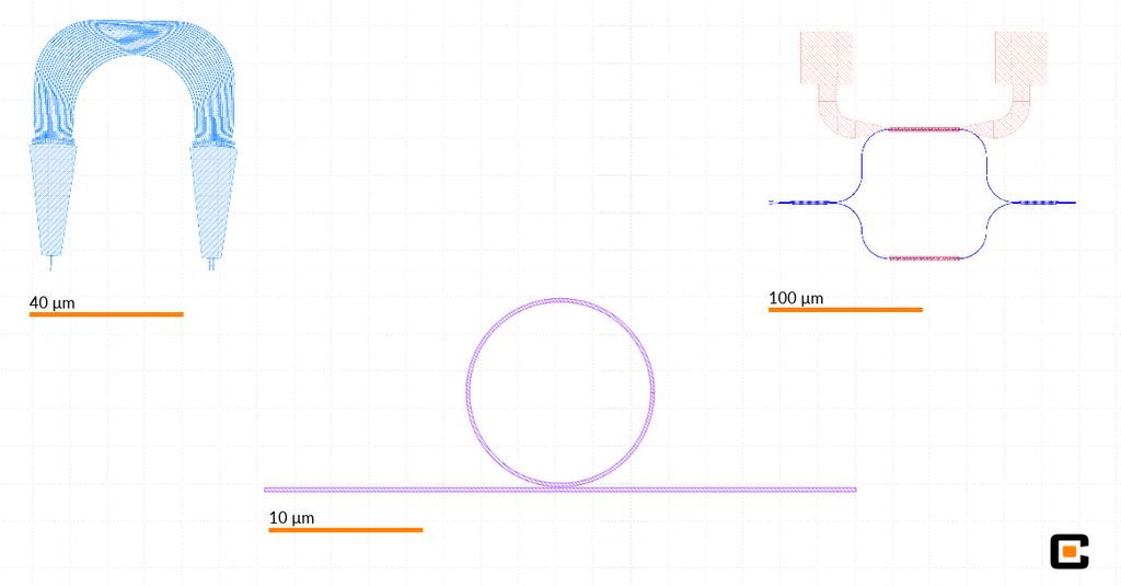
From sorting wavelengths to selecting resonances to controlling interference, these three components show how waveguide geometry and material properties set the optical function of a chip.
The layouts shown are illustrative examples created for this challenge.
Happy Day of Photonics!

