Optical modulators are key building blocks in modern photonic integrated circuits (PICs), enabling the conversion of electrical signals into high-speed optical data. From telecommunications and datacom to sensing, LiDAR, and quantum technologies, the performance of a photonic system is often defined by the performance of its modulators.
Let’s delve into some theory.
What is an optical modulator?
An optical modulator is a device that encodes information onto a light wave by modifying one or more of its properties, such as:
- Intensity (amplitude modulation),
- Phase,
- Frequency,
- Polarization
In integrated photonics, modulators are typically driven electrically and implemented on-chip, allowing high-speed, compact, and scalable solutions suitable for volume manufacturing.
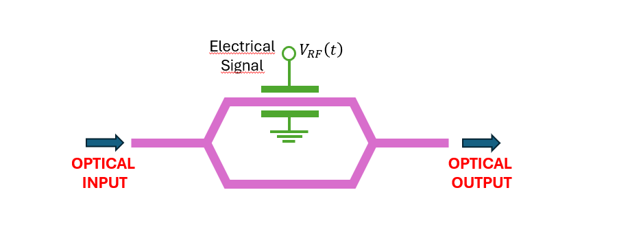
Types of optical modulators in integrated photonics
Depending on the application and platform, different modulator architectures are used:
- Mach–Zehnder Modulators (MZMs): Widely used for high-speed and coherent communications
- Ring Resonator Modulators: Compact footprint and low power consumption, suitable for dense integration
- Electro-Absorption Modulators (EAMs): Common in III-V platforms for short-reach and datacom applications
Each architecture presents trade-offs in bandwidth, footprint, power consumption, linearity, and fabrication tolerance, all aspects that must be considered during the design phase.
Designing modulators
Designing high-performance optical modulators requires expertise in electromagnetic simulation, electrical-optical co-design, and process-aware layout. At VLC Photonics, we support:
- Modulator architecture selection based on application requirements
- Electro-optic simulation and optimization
- Process Design Kit (PDK)-based layout
- Design for manufacturability (DfM) and design for testing (DfT)
Our experience across multiple photonic platforms allows us to guide customers toward designs that balance performance, yield, and scalability.
Materials for optical modulators: choosing the right platform
Selecting the right material platform is critical for modulator performance. Some of the most common options include:
Silicon Photonics (Si)
- CMOS compatibility and large-scale manufacturing
- Plasma dispersion effect modulation
- Well-suited for datacom and telecom
- Trade-off between bandwidth, half-wave voltage (Vπ), and loss
Indium Phosphide (InP)
- Strong electro-optic and electro-absorption effects
- Native light sources and modulators on the same chip
- Ideal for high-performance telecom and coherent systems
Thin Film – Lithium Niobate (TFLN)
- Excellent electro-optic (Pockels) effect
- Ultra-high bandwidth and low loss
- Increasingly popular for next-generation modulators
A real example: a TFLN modulator beyond 110 GHz
To put these principles in context: a travelling-wave TFLN Mach-Zehnder modulator, fabricated on a 400 nm X-cut LNOI wafer through a commercial MPW process, can achieve an EO 3-dB bandwidth exceeding 110 GHz with a half-wave voltage-length product (VπL) of 2.66 V·cm.
The device uses two 50:50 multimode interference (MMI) couplers and a ground-signal-ground (GSG) coplanar waveguide for push-pull operation, with the electrode geometry engineered so that the microwave effective index matches the optical group index (n_g ≈ 2.17). At 90 GBaud PAM4, this kind of device supports data transmission with BER below 10⁻⁴, confirming its suitability for next-generation optical transceivers.
At VLC Photonics, we help customers evaluate which material and integration strategy best fit their application, considering both performance targets and manufacturing constraints.
Electrode design: where modulator bandwidth is won or lost
In a high-speed modulator, the material is only half the story. The electrode design determines whether the device actually reaches its bandwidth potential.
For travelling-wave modulators, three factors dominate the RF performance:
- Velocity matching: the RF signal and the optical signal must travel down the device at the same speed. When the microwave effective index matches the optical group index, the two stay synchronized and the modulation stays efficient across a wide bandwidth.
- Impedance matching: the electrode should present a characteristic impedance close to 50 Ω to minimize reflections and integrate cleanly with standard RF systems.
- RF loss minimization: reducing attenuation along the electrodes preserves the drive signal over the full device length.
Advanced designs use slow-wave slotted electrode structures to achieve velocity matching while keeping RF loss low and impedance well-controlled. These are exactly the trade-offs a modulator designer has to balance, and getting them right is what separates a device that works on paper from one that performs at 800G data rates.
Key performance metrics for optical modulators
When designing or evaluating an optical modulator, several performance metrics are critical:
- Bandwidth (GHz)
- Vπ or Vπ·L (modulation efficiency)
- Insertion optical loss
- Extinction ratio
- Linearity
- Power consumption
- Thermal stability
- RF loss, velocity, and impedance matching
Understanding how these parameters interact is essential not only during design, but also during testing and validation.

Optical modulator testing and characterization
Beyond design, accurate testing and characterization are essential to validate modulator performance and ensure readiness for system integration or volume production.
VLC Photonics offers professional modulator testing services, including:
- Static and dynamic electro-optic measurements
- High-speed bandwidth characterization
- S-parameter and RF performance analysis
- Extinction ratio and insertion loss measurement
- Wafer-level and die-level testing
- Temperature-dependent characterization
Our testing capabilities allow customers to verify design assumptions, compare technologies, and identify performance bottlenecks early in development.
Working on an optical modulator project?
VLC Photonics offers custom PIC design and high-speed characterization services for optical modulators, from initial simulation to full electro-optical testing up to 110 GHz.
From design to validation
Designing a high-speed modulator is one challenge. Proving it performs is another. Once a modulator is designed and fabricated, its electro-optic bandwidth has to be measured with instrumentation that actually reaches those frequencies; a test setup limited to 40 or 67 GHz cannot characterize an 800G device.
Learn how we characterize EO bandwidth up to 110 GHz
Explore our PIC design services


