The visible range of the electromagnetic spectrum is essential for advanced applications such as biomedical sensing, augmented reality or spectroscopy. Given this interest, photonic integrated circuits (PICs) design houses are working tirelessly to develop PICs that can work between 400 and 800 nm. With the help of microfluidics or direct contact with the environment, these devices provide improved Limit of Detection (LoD) for gases and certain particles in a fluid compared with traditional solutions. Additionally, their miniaturized size, several orders of magnitude smaller than conventional systems, which allows to reduce operating costs drastically.
There are ongoing public and private investments to develop supercontinuum light sources, passive components, and photodetectors to build photonic Systems on Chip (SoC) for biomarker and gas detection applications in the visible spectrum. Essential passive photonic structures such as Arrayed Waveguide Gratings (AWG), 3 dB – 90º hybrid couplers, ring resonator, Mach–Zehnder Interferometers (MZI), and spirals are actively being designed for the 400–800 nm wavelength range.
These innovative components are being developed on established platforms such as Silicon Nitride (Si₃N₄), as well as emerging materials like aluminum oxide (Al₂O₃). To verify the performance of the design of the passive components, high-quality external light sources are required.
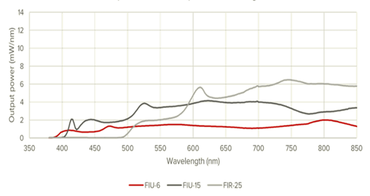
VLC Photonics has implemented a dedicated measurement setup specifically designed for the visible spectrum. This configuration allows measurements between 400 and 800 nm with low insertion losses, ensuring accurate readings above the detection system’s noise floor when using an Optical Spectrum Analyzer (OSA). Our broadband source, a NKT SuperK FIANIUM FIU-6 supercontinuum, provides a wide spectral output with sufficient optical power (0.6 W in the 350 – 850 nm range) for demanding experimental conditions. The supercontinuum spectral output is shown in Fig. 1.
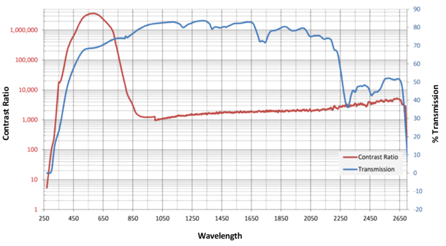
For these measurements in the visible range, polarization control is crucial! Why is polarization control critical for photonic measurements in the visible spectrum? polarization dependent losses (PDL) tend to increase at shorter wavelengths, and therefore a low polarization extinction ratio (PER) has greater impact in the insertion loss measurement compared to the infrared range. To address this challenge, VLC Photonics has acquired broadband polarizers with an extinction ratio exceeding 50 dB in the visible spectrum, which is placed in a fiberbench intersecting with the collimated beam path propagating in free-space. The specifications of the acquired polarization filter can be seen in Fig. 2. The filtered beam is then focused into the PIC waveguides using a microscope objective for facet coupling. Using grating couplers to couple light vertically is also possible, however, this approach requires some development efforts and further consideration as in this case losses could be higher, limiting the dynamic range of measurements. Finally, the output signal is coupled into a visible-range single-mode fiber, which directs the output signal to an OSA featuring 20 picometer resolution and a noise floor as low as -80 dBm.
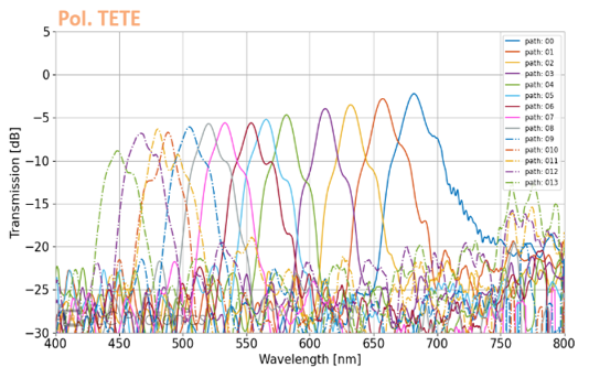
Some of the projects in which this visible wavelength range set-up has been used includes the characterization of structures such as Arrayed Waveguide Gratings (AWGs) and Echelle Gratings. Our custom-designed configuration minimizes insertion losses across the entire bandwidth, enabling accurate measurement of each individual channel. This enhanced performance allows our Optical Spectrum Analyzer (OSA) to detect signals that would otherwise fall below the noise floor in conventional set-ups, where higher losses significantly reduce the output power. A graphical representation of the measurement and the spectral response of each AWG channel is shown in Figure 3.
By leveraging our state-of-the-art optical components and optimized setup design, we are able to perform full-spectrum measurements across the entire visible range in a single acquisition, completely eliminating the need for manual adjustments or component swaps during the measurement. This approach not only significantly reduces the lead time required to obtain accurate spectral data but also accelerates your design iteration cycles. As a result, you can make faster, more informed decisions throughout design and development phases, ensuring your product reaches the market on schedule without compromising quality or performance.
What is the maximum wavelength range that can be measured?
Making use of the NKT broadband source, the measurement can range from 400 nm up to 2700 nm wavelengths. However, in a single measurement, measurements can reach up to 800 nm. For further wavelengths such as 1000 nm it is possible to measure them with the proper set-up changes and calibrations. Note that this increases lead time for your results.
Is there a required pitch separation between the waveguides?
When coupling with microscope objectives (free-space), there is no fixed required pitch between waveguides. In practice, we recommend a100–150 µm separation to ensure reliable alignment and minimize optical crosstalk.
In what conditions can the chips be measured?
Our standard measurements are performed at 25 ºC and 50% HR. However, we can offer high temperature measurements up to 80 ºC. Furthermore, for assembled devices, we offer reliability tests up to 180 ºC and 85% HR compliant with Telcordia standards.
Contact us to discuss how our dedicated measurement setup and custom PIC design services can accelerate your projects. You can also explore our design services and testing capabilities for a complete photonic development solution.